7+ gamewell wiring diagram
The Gamewell Fci AOM-2SF allows a Gamewell-FCI analog addressable fire alarm control to switch an external power supply such as a DC. Remote annunciator installation wiring diagram 8.

10 Lcd Slp Installation Wiring Diagram 11 Lcd Slp Installation Wiring Terminals Honeywell Gamewell Fci S3 Series Manual Page 22 Manualslib
When you make use of.
. Normal Signaling Mode The signal consists of a series of dots and the number and spacing of the dots is the message. - PAGE INTENTIONALLY BLANK. IdentiFiex 610 base analongaddressable IF610-126 Datasheet IF610-126 circuit IF610-126 data sheet.
Gamewell-FCI Eaton HPSA 7100 Brochure. For example this Gamewell Street Fire Alarm Call Box is box number. Board of Contract Appeals.
GAMEWELL-FCI alldatasheet Datasheet Datasheet search site for Electronic. It is your unquestionably own become old to perform reviewing habit. Gamewell If610 Wiring Diagram No responsibility is assumed by Gamewell-FCI for their use.
Aom 2sf wiring diagram Plates Optional 46 46 E3 Series Installation Operation Manual. Gamewell-FCI Emergency Communications Systems ECS. Follow the field wiring diagrams and installation notes in this manual.
Remote Annunciator Installation Wiring Terminals 9. This new site features a fresh look easy navigation full search functionality responsive design and information on new products and focus on your business. When referencing the 7-Way RV Plug diagram make sure you are looking at the plug the way the.
Gamewell-FCI E3-LOC-MR Wiring Diagram. Among guides you could enjoy now is Gamewell Fire Alarm Box Wiring Diagram below. 212 FLPS-7 Installation Wiring Terminals Table 2121 lists the FLPS-7 power supply installation wiring terminals.
Download the guide below print it and keep it in your toolbox for future reference. Print the cabling diagram off and use highlighters in order to trace the routine. Honeywell Gamewell FCI S3 Series Manual Online.
Wiring Diagram Images Detail. Slp-e3 main circuit installation wiring diagram 1. Gamewell-FCI E3-LOC-TEL Wiring Diagram.
Avoid installing equipment where vibrations will occur. Figure 2111 illustrates the FLPS-7 main supply circuit board diagram. Install the equipment in a clean dry environment minimal dust.
Gamewell if602 wiring diagram. 7 PLEASANT STREET MA 01721 Manuals Online. The IdentiFlex IF is suited for small- to medium- for specific wiring requirements.
610 ADDRESSABLE ALARM CONTROL PANEL OPERATION MANUAL 71810 3 10042000 VER.
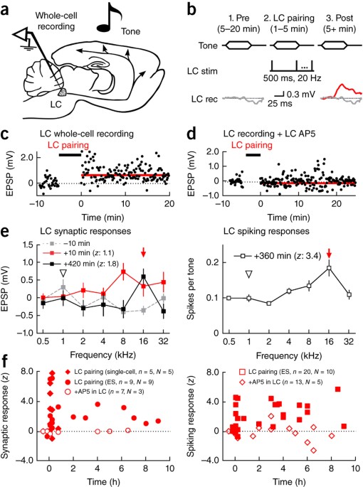
Coordinated Forms Of Noradrenergic Plasticity In The Locus Coeruleus And Primary Auditory Cortex Nature Neuroscience
Honeywell Ul2524 Approved Bda System By Williams Fire Sprinkler Co In Williamston Area Alignable

Observation Of Line Emissions From Ni Like W46 Ions In Wavelength Range Of 7 8 A In The Large Helical Device Iopscience

Advancing Cyclic Ion Mobility Mass Spectrometry Methods For Studying Biomolecules Toward The Conformational Dynamics Of Mega Dalton Protein Aggregates Analytical Chemistry

Amazon Com Johncase Oem Charging Port Dock Connector Flex Cable Microphone Cellular Antenna Vibration Motor Connector Replacement Part Compatible For Iphone 7 Plus All Carriers White Cell Phones Accessories
Gamewell Fci Ms 7af Manual Pull Station Rybb Fire Alarm Parts Service Repairs
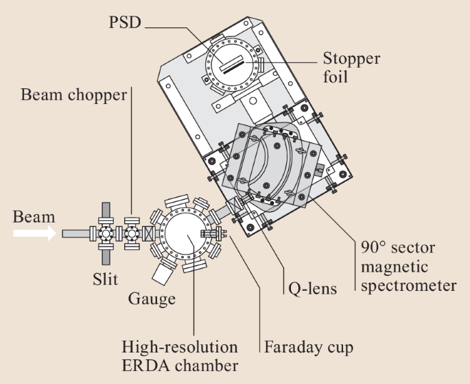
Nuclear Methods In Surface Science Springerlink

Details Schematic Diagram For Iphone 7 7plus Pcb

Electronic Structure Of Ru26 Complexes With Electron Rich Anilinopyridinate Ligands Inorganic Chemistry
Week 11 Dvoa Ratings Football Outsiders
Telephone Patents
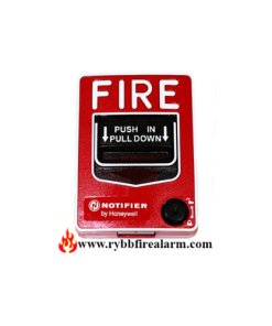
Gamewell Fci Ms 7af Manual Pull Station Rybb Fire Alarm Parts Service Repairs

Honeywell Gamewell 7100 Series Installation Manual 9000 0447 I

Gamewell Fci Ms 7 Series Manual Fire Alarm Pull Stations
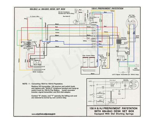
All Wiring Diagrams
Wiring Diagrams Zone All Controls

Nwh 1 9 2015 By Shaw Media Issuu